“All the World’s a Stage, and all the toys and figures merely players” (William Shakespeare if he was a toy photographer)
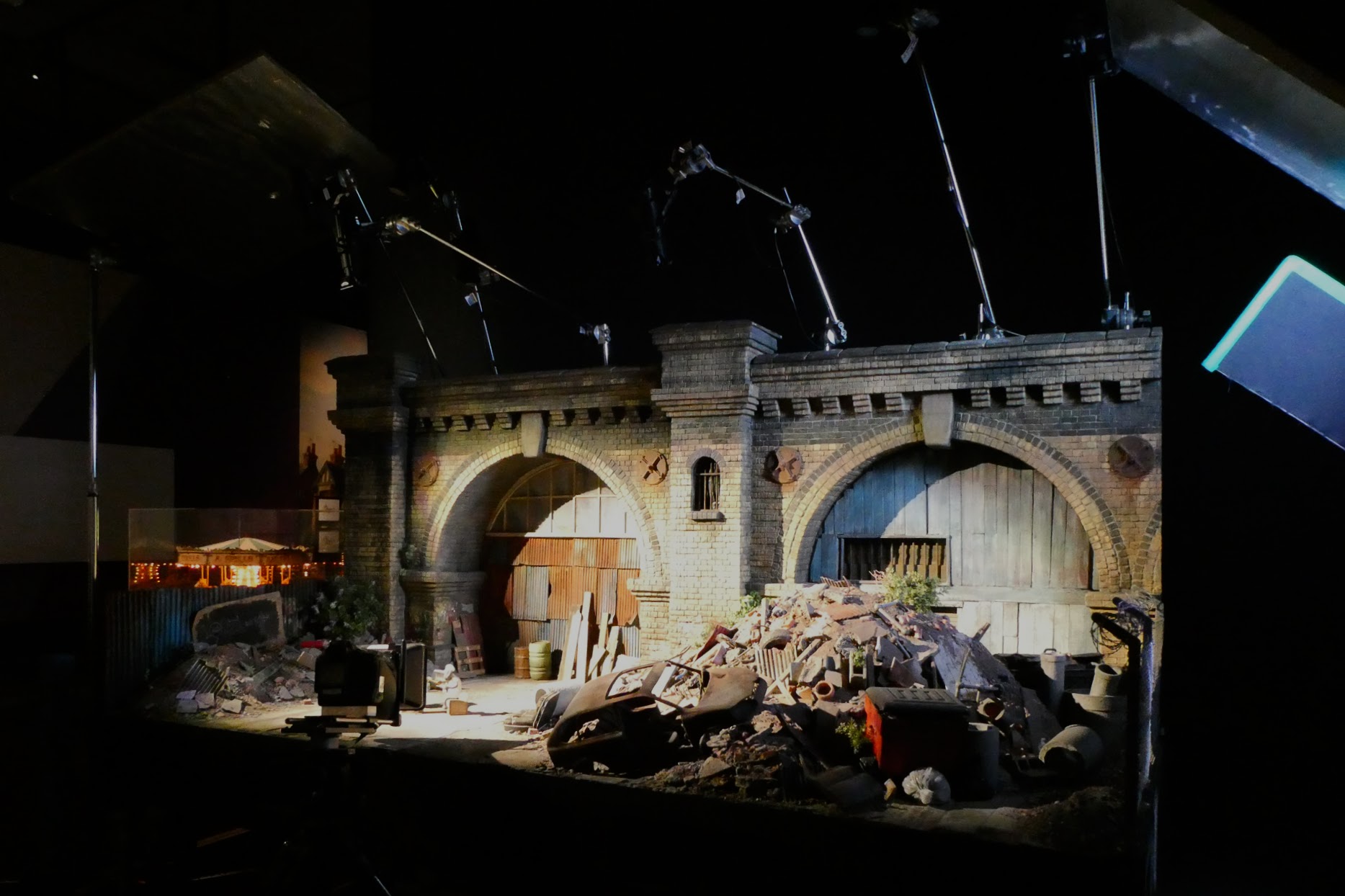
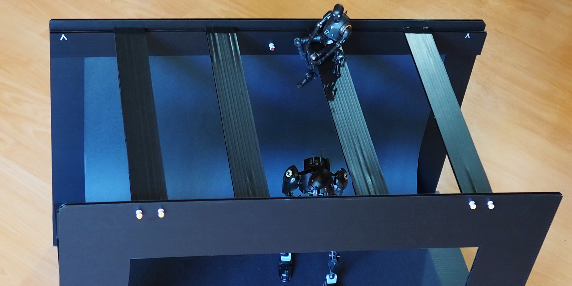
Wallace and Gromit and Friends – lighting set up
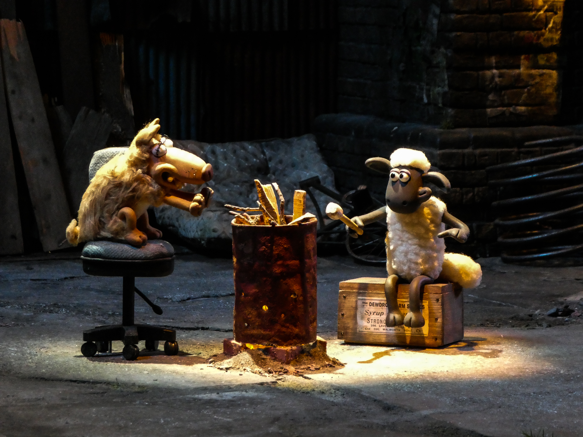
Some time ago I was lucky enough to be able to visit an Aardman exhibition Wallace and Gromit and Friends, which introduced me to the behind the scenes world of stop motion animation. One particular exhibit showed how lighting was used for effect. It consisted of a whole scene set up with camera and lights; showing how different lighting could help tell different stories. Being a toy photographer I easily saw the parallels to what we try to achieve in our photography. That set me on a path to try to replicate the flexibility of this expensive setup in something the hobbyist could both afford and build.
Wallace and Gromit and Friends – lighting set up detail
This is the first of three blog posts which will hopefully inspire you to create your own toy photography lighting stage, complete with lights and backdrops. This post explains how to build the stage; the second discusses the purchase and building of lighting rigs; and the third will give you some ideas on how the lighting can be used for toy portraiture.
I will state, right at the beginning: that the stage I have designed and built, is to suit me. Any materials and dimensions fit my particular circumstances, and you will need to alter these to suit yourself. Hopefully the images and plans provided will give you enough information to build something of value to your photography.
The Lighting Stage – Design and Materials
Although it is possible to make the following design more robust and permanent I decided to allow the stage to be knocked down and packed flat. Not only does it allow those with limited space to store the stage away, it also makes the stage very portable.
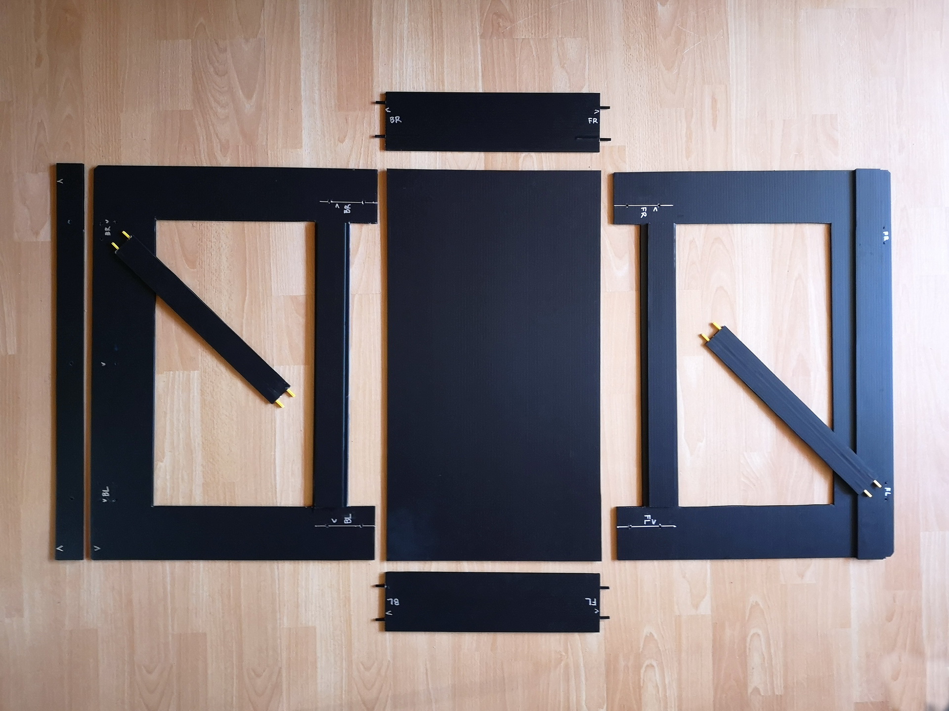
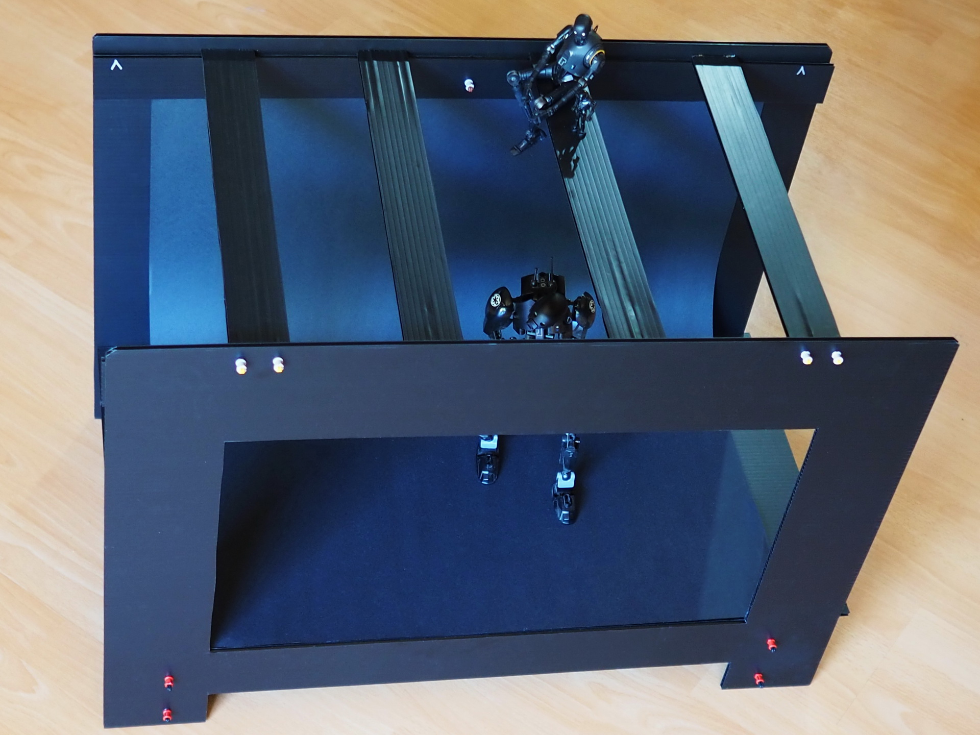
Lighting Stage – ready for assembly
The dimensions of the materials below will make an excellent stage for anything up to six, or so 1/12 scale figures, or many more smaller figures. ⅙ scale figures are a little too large, but it is possible to shoot them effectively in some cases.
I designed the basic frame of the stage to be able to accept paper/card at the back for a background. There is also a cutout (when the paper/card is removed) to frame a 24” computer monitor to allow digital images to be used as backgrounds as well. Both the front and back panels are the same dimensions to allow easy access to the lights, and the subjects while on the stage (the sides of the stage are also completely open for this purpose). The two side stage floor supports, and two top supports are added to the frame to give it strength. The stage floor supports have a second purpose to help hold the floor of the stage. The top supports are also designed to hold lighting rigs (see part 2), above the height of the monitor to avoid reflections. Two more lighting supports (not connected to the frame) are cut to the same dimensions as the top supports. This will allow the lighting rigs to be placed anywhere over the top of the stage.
There are two panel supports attached along the inside lengths of the front and back panels, directly below the top supports. These provide front and back ledges for both the top and lighting supports. They also allow the lighting supports to slide the length between the top supports for flexibility of positioning of the lights. Front and back panel stage floor supports are attached on the inside lengths of the front and back panels, between the left/right stage floor supports. The top edge of the supports align with the top edge of the side battens. The sole purpose of these supports is to help prevent the stage floor from bowing under the weight of any subjects placed on it. I have tested this with 250g (1 lb) weights and the floor holds up easily. That should cover most toys. If you wish to place any more weight on the stage floor I would suggest adding a centre support for extra strength.
I made a prototype from some heavy cardboard packaging that held furniture. This allowed me to play with the design and colouring without having to spend anything The original was pretty much a 300mm (12”) cube made from four pieces of cardboard. Interestingly this proved so handy that I still use it today. Although I have made the final design from 5mm (approx ⅕”) corrugated plastic, there is no reason why you couldn’t use cardboard or foam board (which, in Australia is also 5mm).
The Lighting Stage – Build
Tools for the final build were a long metal ruler, sturdy craft knife, cutting mat, hot glue gun, and a cordless drill with a 4mm (approx 5/32”) drill bit. You can substitute an awl, or other sharp instrument (no wider than 4mm) for the drill. I also used a silver paint pen for marking.
Lighting Stage – complete with background card
For the final version you see here, I used three 770x500mm (approx 30×20”) 5mm corrugated plastic panels. In Australia it is also known by the common name of signboard, or the brand name Corflute. This material is both reasonably robust and easy to work with.
In addition I used:
- sixteen Lego Technic Axle, 8 parts (Bricklink item: 3707);
- three Technic, Axle 3 with Stop parts (Bricklink item: 24316);
- nineteen Technic Bush parts (Bricklink item: 3713).
The axles fit neatly into the channels of the corrugated plastic and the bushes hold the panels onto the axles. The side and top supports have four longer axles, two each end, glued into the channels with about 12mm (½”) protruding from the channels. Holes are drilled through the panels to accept the protruding end of the axles and the bushes are then pushed onto the axles to hold the side and top supports onto the panels. I have found this to be surprisingly effective.
Three of the panel supports are glued onto the panels. The fourth (back panel top support) is attached to the rear panel by the three axles with stops, and three bushes. This allows three holes to be drilled/punched into the background paper or card. The paper/card sits between the rear panel and the support and ‘hangs’ to form a smooth, curved seamless background. The paper/card can easily be removed to allow a monitor to be used for alternate backgrounds.
For added strength I used three thick wooden skewers (not more than 4.4mm or 11/64” in diameter) for each top/lighting support to help take the weight of the lighting rigs and power supplies (see part 2). Push them fully into the channels that are not being used for the axles.
Long notches were cut out of the bottom of both front and back panels. This will allow a monitor stand to sit underneath at the back (for the monitor to sit flush with the back panel) and the computer keyboard, or mini tripod leg to slide underneath at the front. The excess material from the notches can be used for the front and back panel stage floor supports.
Large rectangular holes were also cut in the front and back panels to allow for the monitor screen to be centred in the frame. Cut the back panel hole so approximately 12mm (1/2″) of each monitor edge is covered by the panel. This should hide any top or scroll bars on the monitor. I cut the front panel the same to make the build easier. The bottom of the cutout should align with the top of the stage floor. This will allow any images that include the stage floor to transition naturally to the monitor background. The excess material was cut to make the left/right stage floor, top, and lighting supports.
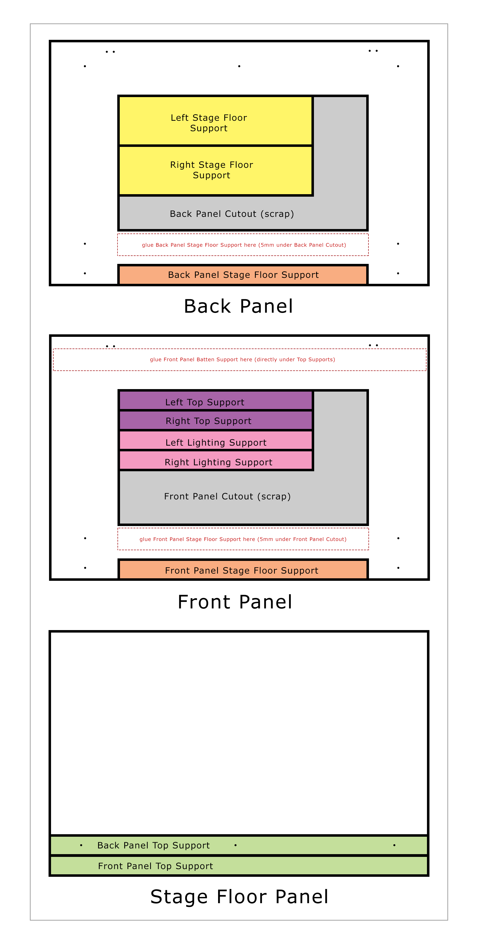
Lighting Stage Panels with instructions on cutting, drilling and gluing
With the panels dimensions suggested, the stage floor can be anything up to 450mm (18”) deep. You will need some excess to cut the top supports to be at least 25mm (1”) wide each. The depth will mainly depend on the amount of space you have in front of your monitor, but I would suggest it is no less than 300mm (12”) to allow for enough separation between your subjects and your background.
I used the entire 500mm for the height of my stage. [Note: I’ll refrain from using fractions of inches in this section] This allowed me to have 110mm (4.33”) height to the top of the stage floor and 90mm (3.25”) for the lights (see part 2) under the lighting rigs to be hidden above the monitor (plus another 15mm or 0.6” above the top/lighting supports). I did cut 70mm (2.75”) off the length of the corrugated plastic panels to fit my desk.
The Lighting Stage – Take-outs
Make everything you can black. The corrugated plastic or cardboard (which I painted black), tripods, camera/lens. This will minimise reflections.
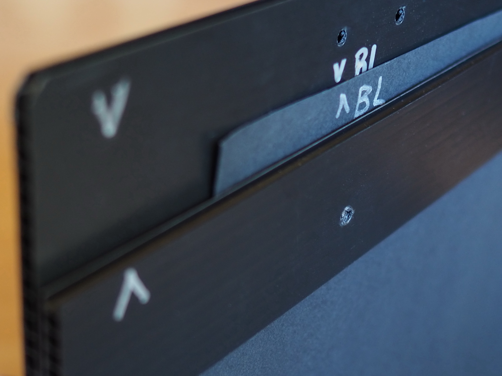
Lighting Stage – connection symbols and text help with reassembly
Mark your parts with alignment symbols and text. I used ‘V’ arrows and notations such as FR (Front Right) and BL (Back Left). You will not get all cuts or holes perfectly aligned and this helps when you put the stage together easily after dismantling.
Beware: the hot glue gun nozzle has the potential to melt the corrugated plastic. It’s not that easy to do, but If you leave it against the plastic for too long it can be a problem.
Deliberately drill through the centre of the channels, otherwise the drill will be pushed that way by the channel walls and throw your measurements out.
The corrugated plastic may have a slight bow towards the centre. Take advantage of this and place the apex of the bow towards the inside of the frame. This helps tighten things up.
Cut the top and lighting supports to 48mm wide. This is the same dimensions as six Lego studs. As the lighting rigs (explained in part 2) are made out of Lego with 6×4 plates, you can see why I am stipulating it here.
I also added a cheap, black plastic party tablecloth and cut it to approximately 1200x1200mm (48”). Attached to the back panel by a couple of small fold back clips, this sheet allows you to block out all ambient light if necessary.
If you are looking for software that will allow you to view images at varied magnifications (for digital backgrounds), then I can recommend Irfanview (irfanview.com). I am not affiliated with this software product, but I have used it for 15 years and have found it extremely useful (and it has heaps of cool image utility functions, including batch processing).
The Lighting Stage – Conclusion
I went through six designs before I settled on this one to share. I feel it is the best compromise of cost (under AU$25, US$20) robustness, portability, and, most importantly: practicality. I am personally very happy with the way it has turned out, and initial presentations to four other toy photographers have been positive. If you decide this design, or some variation of it, is for you, I will be most happy. We would love to read your experiences below in the comments section.

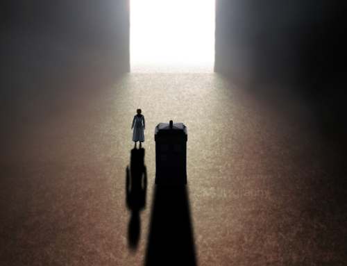
Wow. Fascinating post Tony. That Wallace and Gromit detail shot is incredible. And such gorgeous lighting. Thanks for posting this piece!
Thank you Doug. That exhibit was truly inspirational.
A very detailed article with all the necessary information to build this wonderful stage Tony. I’m fortunate enough to be able to use the setup and most of my recent indoor shoots have been created using it. The base is strong too and I’d even placed a sizeable rock on it (used for last month’s podcast’s #tp_love theme contribution.)
The way it dissembles into a compact flat package is an added bonus, making it really portable and handy in saving space at home (more space for toys! Haha.)
Looking forward to reading the next instalment in lighting.
Cheers Janan. I am so pleased that this stage has been of benefit to you. As you are predominately a shooter of 6″ figures, I am really happy to know that it works well for this scale too.
Very cool, Tony. And inspirng. I like the fact that you used Lego parts for connectors – clever move!
Thank you Tobias. I hope you try one for yourself. The Lego lighting rigs were fun to build.
Looking forward to giving something like this a try, Tony. Thank you so much for taking the time to document your project and share it here!
My pleasure Teddi. Feel free to contact me directly if you have any queries.